My journey through electronics manufacturing has brought me from THT-soldering to SMD-soldering to assembly-services and now reflow-soldering. Reflow-soldering is the process of applying soldering paste either by hand or through a stencil onto a circuit board to then place all the components on top. That assembly will then be evenly heated up for the soldering paste to liquify and solder everything through. This method allows for very fine contacts (0402 resistors are still doable with a steady hand to place) and high component counts. In the past I have used a Hotplate, that would heat up the soldering past to the required temperature.
I decided mostly for the joy of it, secondary for a finer temperature control to build a DIY reflow oven. A fully encased converted Toaster-Oven that can follow a predefined temperature curve to match the soldering pastes specification as best as i can.
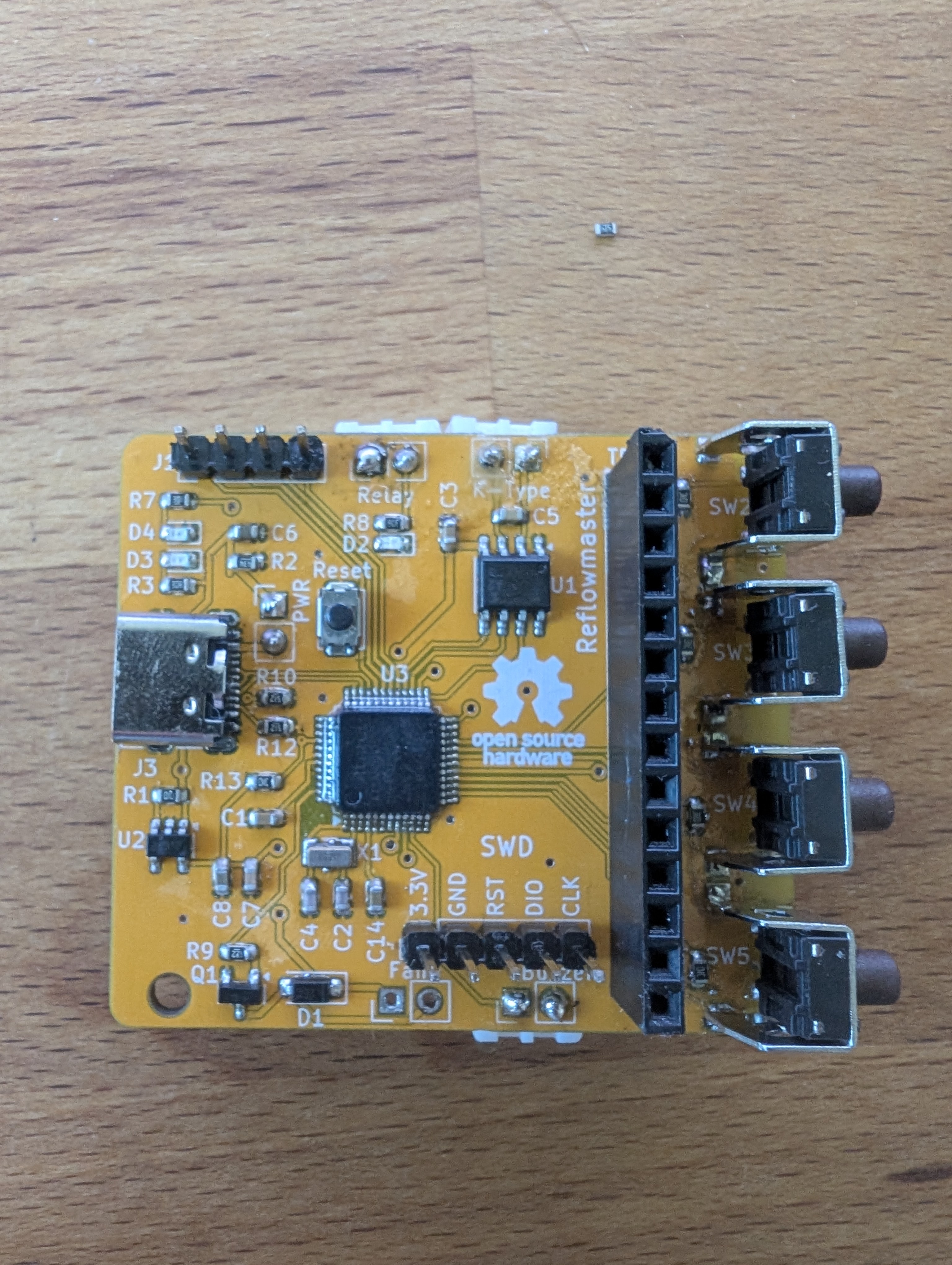
I decided to use the Unexpected Makers Reflow Master. But instead of buing the new fancy version i wanted to assemble my own controller, so i took a look at the now Open-Source predecessor ReflowMaster. I converted his project into kicad and added SWD flashing pins and USB-C into my own Fork.
The electrical layout is almost identical.
I ordered all the parts of LCSC and the PCBs at JLCPCB and procrastinated many
months before finally assembling everything in fear of having made an expensive mistake.
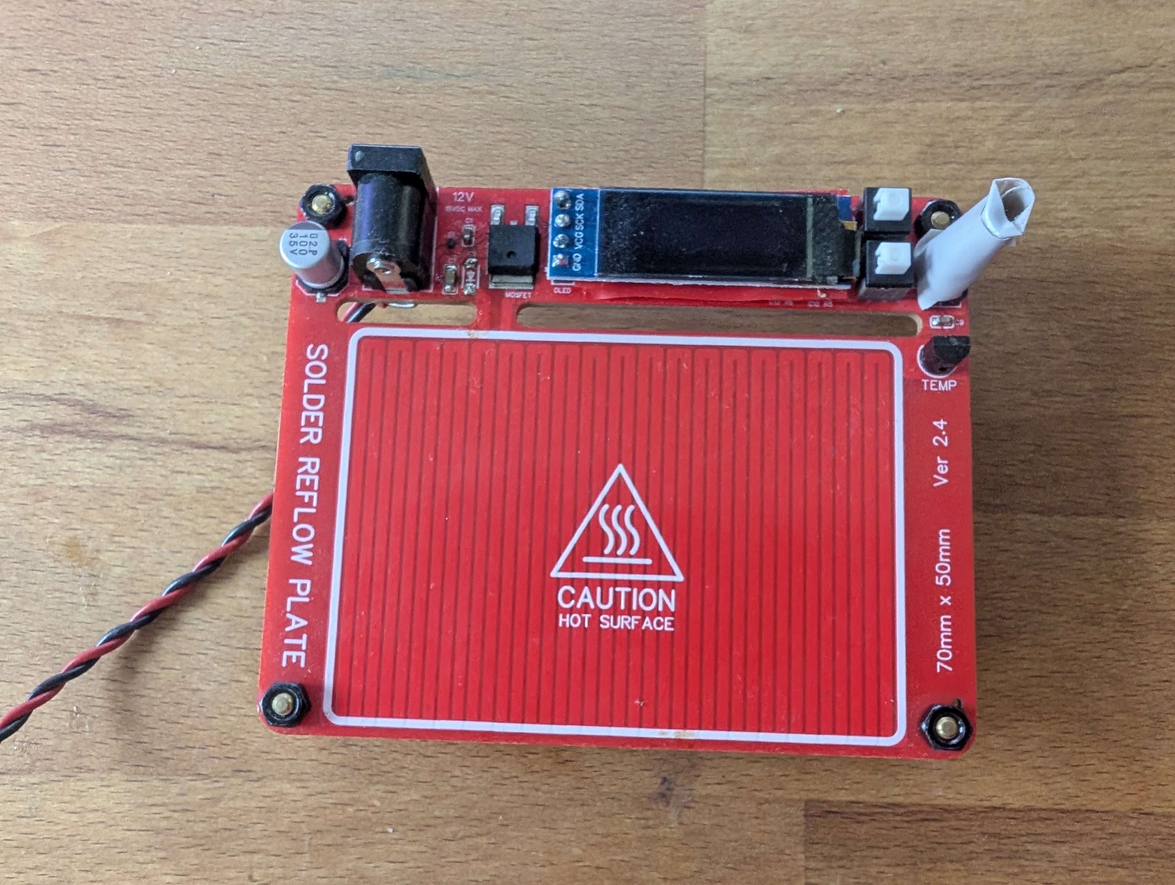
I assembled everything on this DIY hotplate.
Luckily everything worked out of the box including the SWD bootloader and firmware flashing
and my controller is now flashable via USB-C.
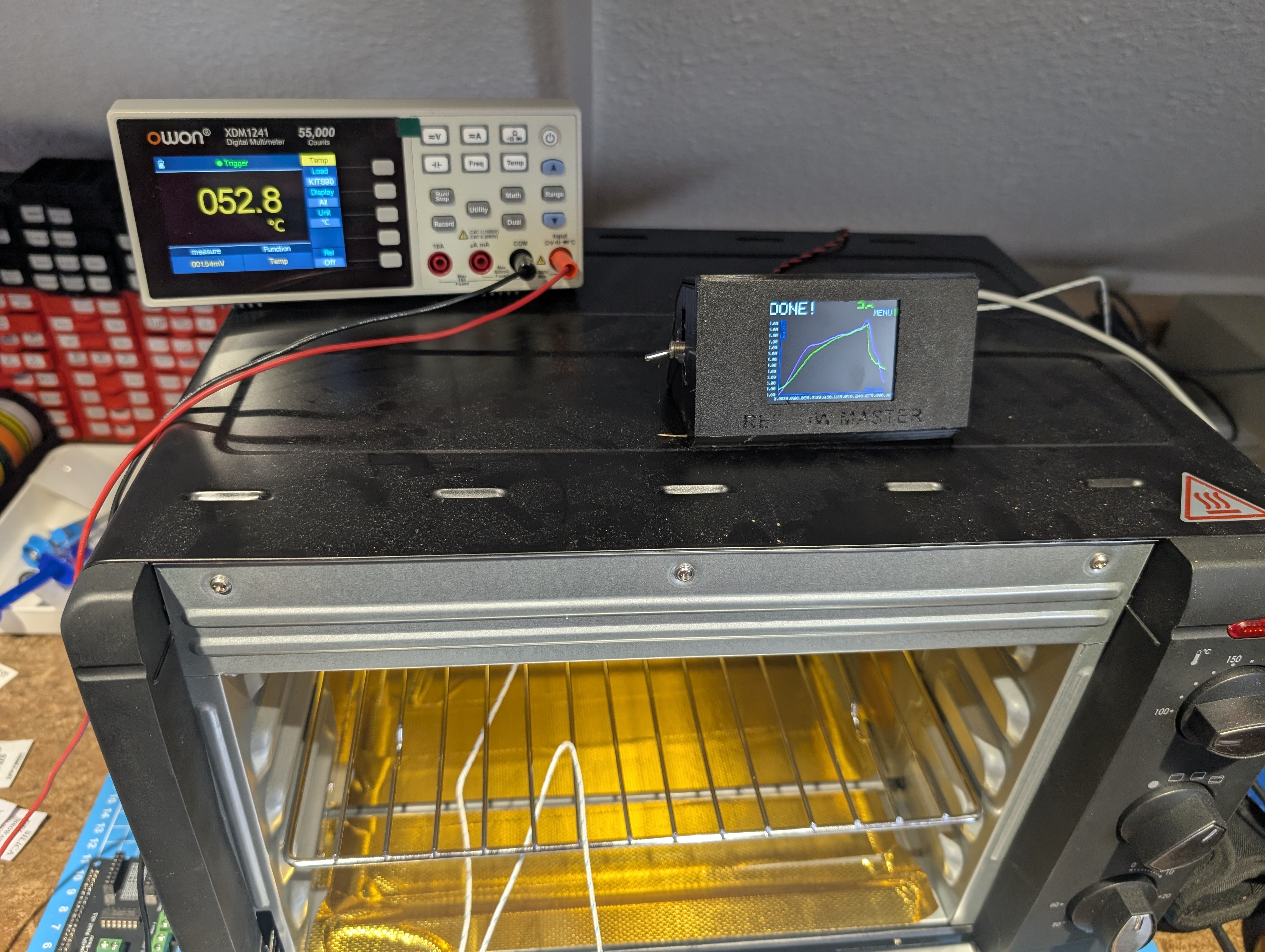
The rest of the hardware is relatively simple and mostly described in other guides for the ReflowMaster. A display on aliexpress, K-Type temperature probes and a solid-state-relay to PWM-control 230V AC using 3.3V DC TTL. The Oven is just a regular Toaster Oven. I found this one for 55€ during a sale of a Supermarket in Germany and with 1.5kW it has just enough power to heat. I covered the inside of the oven in Gold-Foil to reflect as much heat as possible. Without additional insulation-padding between the inside and outside wall the outside oven will not get uncomfortably hot, although a piece of glaswoll or similar would propably improve heating performance.
At this point the oven if functional and passes the firmware tests and I will soon start creating the first test PCBs with it.
If anybody is interested in more details about the electrical design, flashing, assembly or else, please shoot me an email and I'll expand on it